
CLICK HERE TO START INTERACTIVE APPLICATION.
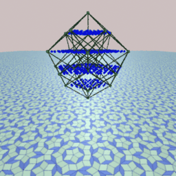
Penrose tilings are well known because of their interesting and sometimes intriguing properties; for example, they are locally but not globally symmetric under 5-fold rotations, quasi-periodic with respect to translations, self-similar, and more. See the references at the end of this document if you want to find more about Penrose tilings. If you do not know what a Penrose tiling is, there is one in the background of the image at the top of this document.
N.G.deBruijn in 1981 showed that Penrose tilings can be seen as the projection of a relatively simple object in 5-dimensional space. QuasiTiler uses deBruijn's approach to generate tilings.
The original version of QuasiTiler is a NeXTSTEP application, with more features than the ones possible to implement over the web. It is available by anonymous ftp from this server. See the reference at the end of this document.
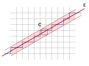
We look now to a region of the plane around the line E. This region is just wide enough to contain any square with side length 1 centered at any point on the line E. We call this region C. Now we select all the points in the lattice that happen to be inside the region C. We also select all the edges that join these selected points. We obtain a funny looking staircase curve as result. Now we project the staircase perpendicularly onto E. Adjacent edges of the staircase collapse to adjacent line segments in E. We have as result a tiling of this one-dimensional space.
Observe that we can choose the line E anyway we want, obtaining a different staircase each time. An important property depends on the slope of E: if we choose the slope of E to be a rational number then the pattern of the staircase and the projected tiling repeats itself periodically; but if the slope is an irrational number the pattern is not periodic. However in this last case, if we choose any piece of the staircase (of finite size) the chosen piece will be repeated an infinite number of times at different places all over the region C: we get a quasiperiodic staircase.
QuasiTiler does exactly the same thing. But instead of using the line E and a square grid on the plane, it uses a plane and an integer lattice in spaces of dimension 3, 4, 5 or more. By passing a higher-dimensional cube along E, we get a 2-dimensional staircase siting in a higher-dimensional space. QuasiTiler then projects the staircase surface onto the plane E. The result is the tiling that you see.
Let's work with the idea in 3 dimensions first: instead of a grid of squares in the plane we consider a 3-dimensional grid of cubes, and a 2-dimensional plane crossing them instead of a line. The vertices of the cubes are the points on the integer lattice. We take a plane E, and as before slice the space with it and look at the region C around the plane E. This region is just wide enough to contain all the cubes of side-length 1 centered at any point in the plane E. We select then all the lattice points inside this region C, together with the corresponding edges and faces. The result is an arrangement of steps, which we project into the plane E. You can see in the next image two different results obtained with QuasiTiler by choosing two different planes.
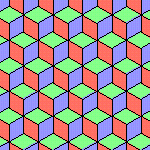
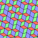
With QuasiTiler we can browse in 4, 5 or more dimensions by taking 2-dimensional "slices" of the corresponding lattice. The results will get more interesting. The more dimensions we have the more things can happen. For example, Penrose tilings are just a particular class of these slices in 5-dimensional space.
QuasiTiler shows also a different view of the same staircase surface sitting in n-dimensional space by projecting it into the space orthogonal (= perpendicular) to the plane E. The lattice points in C all project into the interior of the projection of the n-dimensional cube. The image below corresponds to a Penrose tiling.
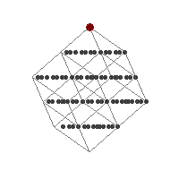
The gray points correspond to the lattice points near the plane E. The region C is represented by the light gray lines, which are the edges of an n-dimensional cube of side-length 1, with n equal to 5 in this particular case. Finally the large red dot represents the origin of the coordinate system, and indicates the position of the plane E and the region C relative to the integer lattice and the ambient space. You are in control of this red dot in the program.
Notice that the orthogonal space to E has dimension n-2, but QuasiTiler shows you only a 2-dimensional view since a computer screen is flat. This is good enough in most cases anyway. However there is room to improve this flat view. For example, the image at the top of this document shows a 3-dimensional view in perspective of the same object represented in the image above.
The plane E is specified by one position vector and two direction vectors. In QuasiTiler, we call the position vector the offset, and the two direction vectors the generators. There are some conditions that we are going to impose on these vectors. The first condition is that the two generators need to be linearly independent; this is a necessary condition, otherwise we would get a line instead of a plane. The next condition is that that the generators are orthogonal to each other and of length 1; this is not necessary, but it will be helpful, as we will see later. The final condition is that offset has to be orthogonal to the plane E; this condition is just to simplify the computations. QuasiTiler allows you to enter the numbers directly, and makes sure that all the conditions are satisfied.
To ensure that the offset is orthogonal to the plane E, the offset vector is always represented as a vector in the orthogonal complement of the plane E, which is an (n-2)-dimensional space. The position of the large red dot in QuasiTiler's offset control is determined by the first two coordinates of the offset.
Let's see now the advantages of having the generators orthogonal to each other and of length 1. We consider the canonical basis of the ambient space. The canonical basis is just the vectors of the form
     ( 1, 0, 0, . . . ),
     ( 0, 1, 0, . . . ),
     ( 0, 0, 1, . . . ), . . .
When the condition on the generators is satisfied, we can tell right away the coordinates of the projection onto the plane E of the k-th canonical basis vector; these coordinates are the same as the k-th coordinates of the two generators. And these projections of the canonical basis are important for us, since they are precisely the edges of our tiles, as we explain next.
Remember that the edges of the surface in the higher dimensional space are just the edge of some n-dimensional cube with integer coordinates vertices. And the edges of any of these n-dimensional cubes are a translation of one of the vectors in the canonical basis, which are then projected onto the plane E. Thus all the edges in the tiling are just the projection of one of the vectors from the canonical basis translated to the corresponding vertex. Furthermore any tile is just a parallelogram determined by a pair of these edges. In other words, the projections of the canonical basis give the coordinates to build the tiles.

In this image you can see the relative positions of the lattice points inside the region R. The view is a projection into two of the orthogonal directions to the generating plane. You are in control of the red dot, which represents the center of the coordinate system, the origin. Whenever you select a point in this image the origin will move there; the offset of the plane E will change correspondingly. Keep in mind that this method you can only change two coordinates of the offset vector, however this gives more than enough room to explore.
If you insist on changing the offset in all its coordinates you can use the second method. At the bottom of the form there are three columns of numbers. The coordinates of the offset vector are on the first column. Type any values you want and submit the form when you are done. On the technical side, this vector is expressed in the coordinates of the space orthogonal to the generating plane.
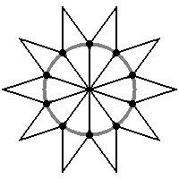
The fat points in the image represent the projection of the canonical basis of the ambient space into the generating plane. When you select a point in this image, the program will move the generating plane so that the nearest fat point will move as close as possible to your selection, dragging with it the shape of the tiles. Some directions and shapes will give more pleasing tilings than others. The default values produce tiles symmetric under rotations.
As with the offset, it is possible for you to change the coordinates of generators directly. The coordinates of each generator are on the two columns at the end of the form. Type any values you want and submit the form when you are done. Notice that there are some conditions that must be satisfied by these numbers; QuasiTiler modifies your input to enforce those conditions. This is explained in a previous section.
Please send me your comments, I am looking forward to them.
Martin Gardner, Penrose Tiles to Trapdoor Ciphers, W.H.Freeman, New York, 1989.
Roger Penrose, The Emperor's New Mind, Oxford University Press, New York, 1989. Yes, he is the same Penrose as in "Penrose tiles." The tiles are mention only briefly though.
N.G.deBruijn, Algebraic theory of Penrose's nonperiodic tilings of the plane, I, II, Nederl. Akad. Wetensch. Indag. Math. 43 (1981) 39-52, 53-66. This is deBruijn original paper, hard to read.
Stan Wagon, Mathematica in Action, W.H.Freeman, New York, 1991, chapter 4. Here you can find how to generate Penrose tilings using the Mathematica software, together with a nice explanation of some of their properties. The approach used here is different from QuasiTiler. It has further references too.
Ivars Peterson, The Mathematical Tourist: Snapshots of Modern Mathematics, chapter 7, W.H.Freeman, New York, 1988. Here the book's author stops short of exploring the same ideas as in this document.
Marjorie Senechal, Quasicrystals and Geometry, Cambridge University Press, 1995. To appear.
D. R. Nelson, Quasicrystals, Scientific American, 255 (August 1986) 42-51.
D. R. Nelson and B. I. Halperin, Pentagonal and icosahedral order in rapidly cooled metals, Science, 229 (19 July 1985) 233-238.
Check also a another explanation to the mathematics behind QuasiTiler, by Prof. Marjorie Senechal, an expert on the subject.
QuasiTiler is also available as a NeXTSTEP application by anonymous ftp from the Geometry Center FTP. To download the Multi-Architecture Binary (Motorola, Intel, HP PA-RISC) /pub/software/QuasiTiler-3.0.tar.Z click here.
Any comments and suggestions concerning this web server are welcome and should be e-mailed to webmaster@geom.umn.edu.
The Geometry Center
University of Minnesota
400 Lind Hall
207 Church Street S.E.
Minneapolis, MN  55455