Beam Support
In this module, we will consider two different methods for supporting a beam. The
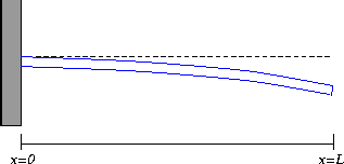
first method is called a cantilever , which is obtained by firmly
clamping or bolting the beam at one of its ends, and allowing the beam
to hang freely on the other end. The second method is called a
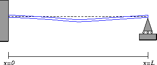
simply-supported beam. In this case, the beam is placed upon two
supporting structures and the beam is pinned so that it can flex, but
not translate.
In the model of static beams we use in this lab, the deflection of a beam
is describe by a deflection function w(x) .
The value of w (x ) is the amount of vertical displacement
at the position on the beam x units from the left end.
The way the beam is supported translates into conditions on the
function w (x ) and its derivatives. These conditions are
collectively referred to as boundary conditions .
Boundary Conditions and Beam Supports
In the exposition that follows, we will let L be the total
length of the beam and we let x measure the position along
the beam (with x=0 being the left-hand endpoint of the
beam.)
The values of w (x ) and its derivative all have physical
interpretations relating to the way a beam is supported. Here is a
"dictionary" to help translate between boundary conditions and
supports:
- w (x ) -- This is just the height of the beam.
- w' (x ) -- As we know from calculus, w'
indicates the slope of the beam at x . Nothing mysterious
here.
- w" (x ) -- In calculus terms, w" measures the
curvature of the graph of w (x ). Intuitively,
the larger w" (x ) is, more more curved the graph. In physical
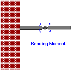
terms, w" (x ) measures the bending moment of the
beam at x . This is the torque that the load places on the beam
at x . One way to think about this is to imagine the beam with a
very stiff hinge in it, as shown below.

The load on the beam to the right of the hinge will exert a torque on
the hinge, tending to rotate it. Even in a solid beam without a hinge, the
beam will tend to bend. How much it bends depends on the
magnitude of the bending moment, and the modulus of elasticity of the
beam material.
- w''' (x ) -- The third derivative has a less intuitive
meaning about the geometry of a curve than w' and w" .
However, it has a fairly straight forward physical interpretation.
Just as w" (x ) measured the bending moment at x ,
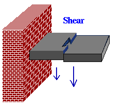
w''' (x ) measures the shearing force on the beam
at x . If we think of our beam with a dovetail joint in it
instead of a hinge, then the difference in forces immediately to the right
and left of the joint will
tend to slide it apart vertically. (In fact, it is the difference in
bending moments, since w''' is the derivative of w" .) This
shearing force is measured by w''' (x ).

Cantilevered Beams

For a cantilevered beam, the boundary conditions are as follows:
- w(0)=0 . This boundary condition says that the base of
the beam (at the wall) does not experience any deflection.
- w'(0)=0 . We also assume that the beam at the wall is
horizontal, so that the derivative of the deflection function
is zero at that point.
- w''(L)=0 . This boundary condition models the assumption
that there is no bending moment at the free end of the cantilever.
- w'''(L)=0 . This boundary condition models the
assumption that there is no shearing force acting at the free end of
the beam.
If a concentrated force is applied to the free end of the beam (for
example, a weight of mass m is hung on the free end), then
this induces a shear on the end of the beam. Consequently, the
the fourth boundary condition is no longer valid, and is typically
replaced by the condition
where g is the acceleration due to gravity (approximately 9.8
m/s2).
We note that we could actually use this boundary condition all the time, since if
m=0 , it reduces to the previous case.
Simply-Supported Beams

For a simply-supported beam, we use the following boundary conditions:
- w(0)=0 . Because the beam is pinned to its support, the
beam cannot experience deflection at the left-hand support.
- w(L)=0 . The beam is also pinned at the right-hand support.
- w''(0)=0 . As for the cantilevered beam, this boundary
condition says that the beam is free to rotate and does not experience any
torque. In real life, there is usually a small torque due to friction
between the beam and its pin, but if the pin is well-greased,
this torque may be ignored.
- w''(L)=0 . In the same way, the beam does not experience
and bending moments on its right-hand attachment.
Other Beam Supports

There are many other mechanisms for supporting beams. For example,
both ends of the beam may be clamped to a wall. Or one end may be
bolted and the other end is free to rotate. Or the beam may be
clamped at one end but "overhang" a support placed at some point along
its length.
Each of these support mechanisms have associated boundary conditions,
but we will not pursue these mechanisms here.
Return to: Main Ideas of the Lab
The Geometry Center Calculus Development Team
Copyright 1996 by The Geometry Center.
Last modified: Fri Apr 12 15:54:29 1996


